Wheatstone Bridge Gain Equation
Although the electronics industry is relentlessly driven by advances in materials components and architectures the new obviously also builds on the old and often still uses it albeit in new guises. A wheatstone bridge is an electrical circuit used to measure an unknown electrical resistance by balancing two legs of a bridge circuit.

Bridge Circuits Dc Metering Circuits Electronics Textbook

Design Notebook Linearization Of A Wheatstone Bridge

Op Amp Differential Amplifier Circuit Voltage Subtractor
The desired value of r x is now known to be given as.

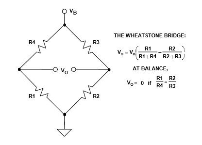
Wheatstone bridge gain equation. The bridge is balanced and ig 0 so the second set of equations can be rewritten as. The wheatstone bridge is the electrical equivalent of two parallel voltage divider circuits. The wheatstone bridge circuit is nothing more than two simple.
Principles and basic applications. The primary benefit of the circuit is its ability to provide extremely accurate measurements. R1 and r2 compose one voltage divider circuit and r4 and r3 compose the second voltage divider circuit.
The wheatstone bridge consists of four resistances r1 r2 r3 and r4 an excitation voltage and an output voltage. From the first rule i 3 i x and i 1 i 2. If we ignore the wheatstone bridge to the left focusing on the differential amplifier i know that the stack exchange network stack exchange network consists of 175 qa communities including stack overflow the largest most trusted online community for developers to learn share their knowledge and build their careers.
A wheatstone bridge is an electrical circuit used to measure an unknown electrical resistance by balancing two legs of a bridge circuit one leg of which includes the unknown component. Wheatstone bridge part 1. Then the equations are divided and rearranged giving.
The wheatstone bridge or resistance bridge circuit can be used in a number of applications and today with modern operational amplifiers we can use the wheatstone bridge circuit to interface various transducers and sensors to these amplifier circuits. The wheatstone bridge was invented by samuel hunter christie in 1833 and improved and popularized by sir charles wheatstone in 1843. If all four resistor values and the supply voltage vs are known.
The output of a wheatstone bridge is measured between the middle nodes of the two voltage dividers. One of the wheatstone bridges. Its operation is similar to the original potentiometer.

What Is A Wheatstone Bridge And Other Strain Gauges Circuits

Op Amp Differential Amplifier Circuit Voltage Subtractor

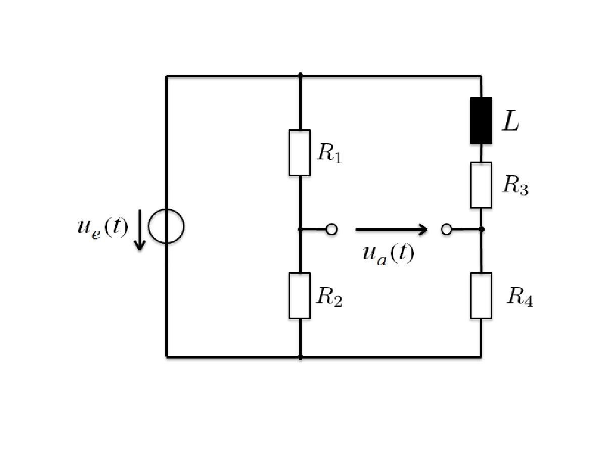
Differential Equation From A Wheatstone Bridge With Inductor

Wheatstone Bridge Single Element Varying Electrical

Stay Out Of Deep Water When Designing With Bridge Sensors

Wien Bridge Oscillator Tutorial And Theory
Applying The Wheatstone Bridge Circuit

Strain Gauges Wheatstone Bridge Network Download

Wheatstone Bridge Part 1 Principles And Basic Applications

Wheatstone Bridge Circuit Equations And Derivation

To Build And Test A Circuit That Converts Resistan

Higher Physics Unit 2 2 4analogue Electronics Op Amp An
Comments
Post a Comment